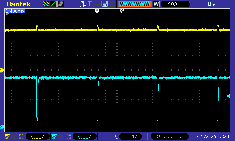
When testing the charge circuit, something didn’t seem quite right…
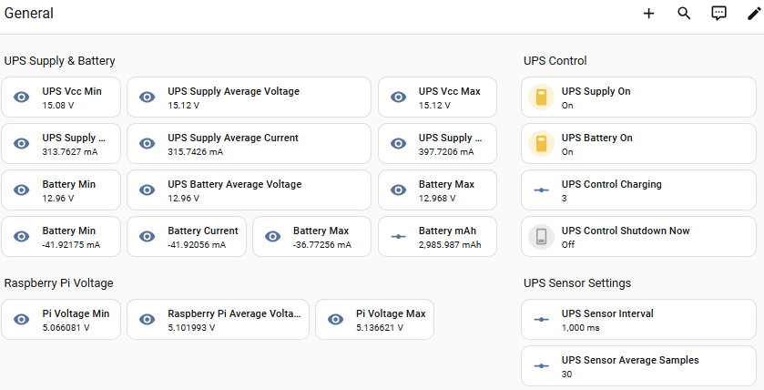
The battery current was about 40mA even though the charging duty cycle was set to 3 (with a maximum of 255). A duty cycle of 3 should mean that the battery is charging for about 12us and not charging for the other 988us (the PWM should be running at 1kHz). If this was correct, it would mean that the current in the on phase was 3.4A (40mA * 255 / 3). Since the charging was via a 13Ω resistor, this seemed unlikely.
So I decided to look at what was happening on a oscilloscope. This is what I got:
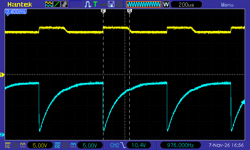
The yellow trace is the battery voltage, the blue trace is the voltage on the input of the MOSFET (M1).
Rather than 12us, the MOSFET was on for about 400us. Looking at the schematic it was clear that 100kΩ combined with the MOSFET gate capacitance meant that the MOSFET switched off far too slowly. I replaced the resistor with a 5kΩ resistor, and things looked a lot better: