
I decided to have an uninterruptible power supply (UPS) for my Home Assistant (running on a Raspberry Pi). The design I came up with is shown below:
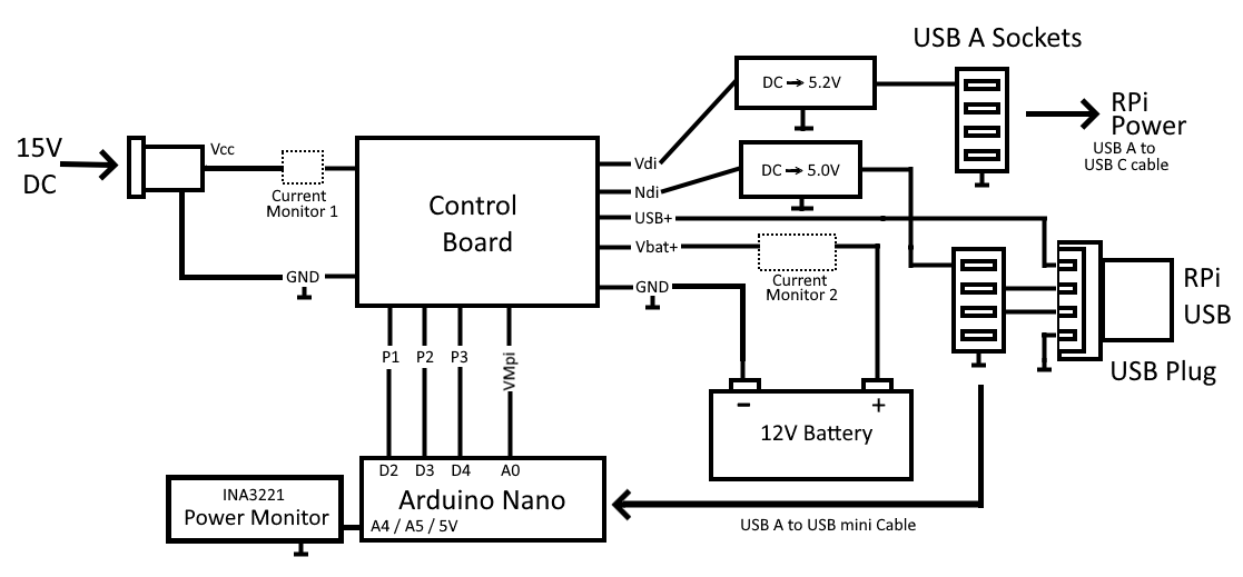
The input from the mains is supplied by a 15V AC to DC adapter (wall wart). This is shown as Vcc/Vss on the diagram above. There are two DC to DC converters, one that powers the Raspberry Pi and one that powers an Arduino Nano. The rPi converter is a LM2596 and the Nano converter is a smaller device (which says it can deliver 3A but it only needs to deliver about 20mA).
The Arduino Nano would always be powered - if the mains if off for longer than the battery can keep that going then we have bigger problems 😟.
The INA3221 power monitor allows us to measure the voltage and current being supplied by the 15V from the mains adapter. If the mains is interrupted this voltage will drop to 0V. We are also monitoring the battery voltage and current. This will show us the charge on the battery (voltage) as well as how much current the battery is supplying (positive current) or how much current is being used to charge it (negative current). The INA3221 can measure up to 26V and ±1.6A. Since we are measuring the current on the input side of the DC to DC converter, this works out to about ±3A on the output side. This should be sufficient under normal conditions for a Raspberry Pi 4. [We don’t measure the current on the output side of the DC to DC converter mainly because that would cause an undesired voltage drop, amongst other reasons…].
The USB+ input allows us to measure the 5V being supplied to the Raspberry Pi. This goes via a voltage divider to the Arduino Nano (VMpi). This gives us the potential to check for the voltage being too low (<4.75) or too high (>5.5V).
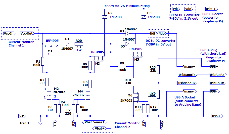
The control outputs allow us to stop the battery charging (P1), disconnect the mains supply (P2) and/or disconnect the battery input to the Raspberry Pi power (P3). Note that we need to be able to cut the power to the Raspberry Pi completely; Although we will instruct the Raspberry Pi to shut itself down, we need to power down and then power up for the Raspberry Pi to start up again.
The schematic for the control board is as follows:
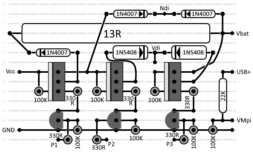
I decided to build the controller board on a PCB prototype board. The layout for this is as follows:
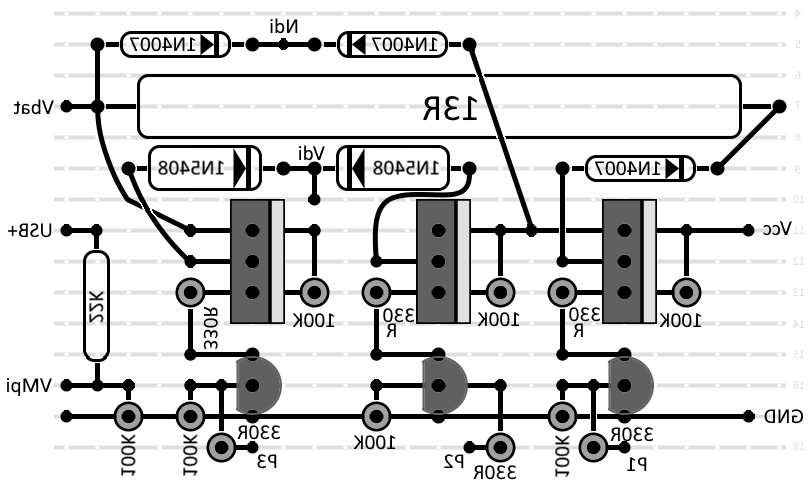
And the reverse side:
The components will be housed in a 3D printed case - that I haven’t designed yet.
The prototype for the software can be found here. I haven’t written the actual software yet, but it would need the following features:
- We pass all the information back to Home Assistant (HA).
- If the power goes off for a short time, we just run on the battery.
- Past a certain amount of time, HA decides to shutdown cleanly.
- The Arduino Nano detects that the HA has shut down and disconnects the power.
- When the power is restored, the Nano decides whether to power up the HA, or wait.
Information passed back to Home Assistant should include voltages and currents and control settings. Control going the other maybe should be virtual switches as the Nano might override the actual settings.