Home Assistant Serial Link to an Arduino
The purpose of this project was to connect an Arduino Nano to the USB port that Home Assistant was running on. For me that is a Raspberry Pi 4 but this solution should work with any Home Assistant hardware. And the reason for using a serial connection over USB (rather than wirelessly with WiFi or similar) could be for many reasons:
- Wifi may not be available (e.g. if the network is down)
- It is more secure
- It is un-jammable
The ultimate plan for me was to create an uninterruptable power supply for Home Assistant from bits that I had:
- A 12V lead acid battery
- A 15V mains adapter
- A DC - DC converter to provide the 5V supply to the Raspberry Pi
- An Arduino Nano as the UPS controller
And the reason for using serial over USB for me was that if the power went down there would be no WiFi (unless I powered the WiFi router from the UPS which I didn’t want to do).
So the solution that I came up with looked like this:
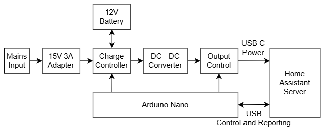
The Arduino Nano is always powered and running - with the watchdog enabled. But before I started on the UPS, I decided to create a proof of concept to test the Home Assistant to Arduino communication. So for this I created the following on a breadboard:
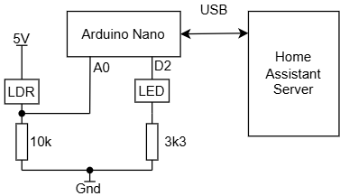
The LDR (light dependent resistor) is used to sense the ambient light level, and the LED is programmable to blink with an interval and duration.
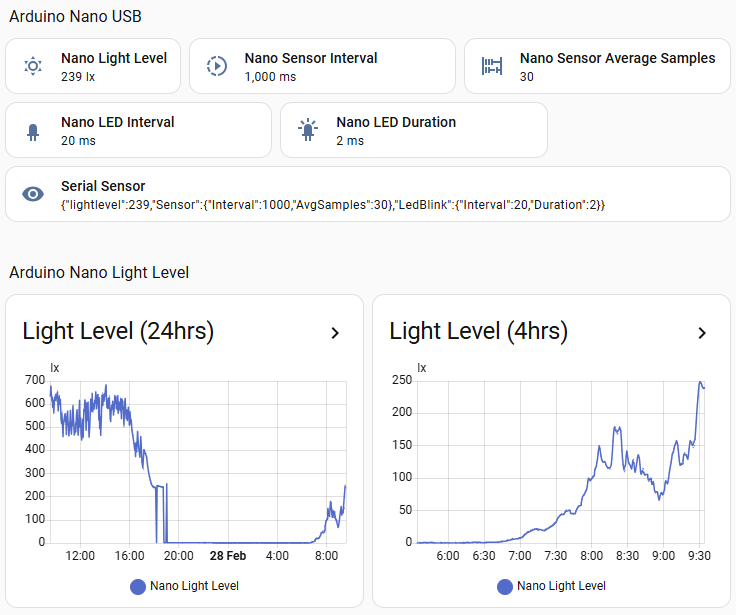
The software is based on the Home Assistant Serial Integration. I decided that the return from the Arduino would be encoded as JSON:
1{"lightlevel":472,"Sensor":{"Interval":1000,"AvgSamples":30},"LedBlink":{"Interval":500,"Duration":50}}
The JSON response includes the LDR value, LDR sample rate (Interval) and sample average (AvgSamples). These last two numbers multiplied together give the sensor update rate (in this case 30 seconds). The LED blink interval and duration are reported back to HA, but also the LED blinks at the specified rate.
The serial integration allows you to create sensors, but does not allow you to send commands. However, you can send commands using the Home Assistant Shell Command. Example commands would look like:
- echo ‘ss1000,30;’ > /dev/ttyUSB0
- echo ‘sl500,50;’ > /dev/ttyUSB0
To test these, they can be sent via the Home Assistant Terminal Add-On.
To receive the serial data and decode it, and send commands, I modified the configuration.yaml file as follows:
1sensor:
2  - platform: serial
3    serial_port: /dev/ttyUSB0
4
5shell_command:
6  set_sensor: /config/nano-send-command.sh "ss" {{ interval }} {{ samples }}
7  set_led_blink: /config/nano-send-command.sh "sl" {{ interval }} {{ duration }}
8
9template: !include template.yaml
And I created a Template.yaml file with the following contents:
 1### template.yaml
 2
 3- sensor:
 4  - name: Nano Light Level
 5    state: "{{ state_attr('sensor.serial_sensor', 'lightlevel') }}"
 6    unique_id: nano_light_level
 7    unit_of_measurement: lx
 8- number:
 9  - name: Nano Sensor Interval
10    unique_id: nano_sensor_interval
11    state: "{{ state_attr('sensor.serial_sensor', 'Sensor').Interval }}"
12    set_value:
13      - action: script.set_sensor_interval
14        data:
15          interval: "{{ value }}"
16          samples: "{{ state_attr('sensor.serial_sensor', 'Sensor').AvgSamples }}"
17    step: 1
18    min: 100
19    max: 60000
20    unit_of_measurement: ms
21- number:
22  - name: Nano Sensor Average Samples
23    unique_id: nano_sensor_avg_samples
24    state: "{{ state_attr('sensor.serial_sensor', 'Sensor').AvgSamples }}"
25    set_value:
26      - action: script.set_sensor_interval
27        data:
28          interval: "{{ state_attr('sensor.serial_sensor', 'Sensor').Interval }}"
29          samples: "{{ value }}"
30    step: 1
31    min: 1
32    max: 60000
33- number:
34  - name: Nano LED Interval
35    unique_id: nano_led_interval
36    state: "{{ state_attr('sensor.serial_sensor', 'LedBlink').Interval }}"
37    set_value:
38      - action: script.set_led_blink_interval
39        data:
40          interval: "{{ value }}"
41          duration: "{{ state_attr('sensor.serial_sensor', 'LedBlink').Duration }}"
42    step: 1
43    min: 1
44    max: 60000
45    unit_of_measurement: ms
46- number:
47  - name: Nano LED Duration
48    unique_id: nano_led_duration
49    state: "{{ state_attr('sensor.serial_sensor', 'LedBlink').Duration }}"
50    set_value:
51      - action: script.set_led_blink_interval
52        data:
53          interval: "{{ state_attr('sensor.serial_sensor', 'LedBlink').Interval }}"
54          duration: "{{ value }}"
55    step: 1
56    min: 1
57    max: 60000
58    unit_of_measurement: ms
The shell commands call a bash script which I put in the config directory:
1#!/bin/bash
2
3#echo "$1$2,$3;" > /config/abc.txt
4
5echo "$1$2,$3;" > /dev/ttyUSB0
Note the commented out echo command to a file. This allowed me to do some simple testing, in case I needed to. Also, make sure that the line endings in the File Editor are set to Unix (LF), not Auto or Windows (CRLF) otherwise the script won’t work. Unix is not necessarily the default (which I think it should be).
The sensors (in the template.yaml file) have a set_value action which calls a script. The scripts file looks like this:
 1set_sensor_interval:
 2  alias: Set Sensor Interval
 3  sequence:
 4  - action: shell_command.set_sensor
 5    metadata: {}
 6    data:
 7      interval: '{{ interval }}'
 8      samples: '{{ samples }}'
 9  mode: single
10set_led_blink_interval:
11  alias: Set LED Blink Interval
12  sequence:
13  - action: shell_command.set_led_blink
14    metadata: {}
15    data:
16      interval: '{{ interval }}'
17      duration: '{{ duration }}'
18  mode: single
Note that I have used the same parameter names in the scripts and the shell commands. You don’t have to do this, and it might have been clearer if they were different. I might refactor this at some point…
I could then add these sensors to a dashboard:
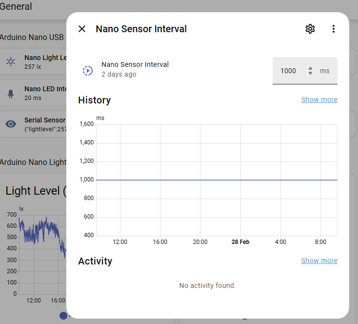
The sensor numbers could be changed by clicking on them which showed the following dialog:
For the Arduino code, I created two classes, Task and Command. Tasks are timed with an interval and duration (typically). Commands process messages sent from Home Assistant.
The entire code for the Arduino can be found on Github, see below.
In part 2 of this article, I will show the UPS circuit in detail and the testing I did on it (but I haven’t done that yet ;).